
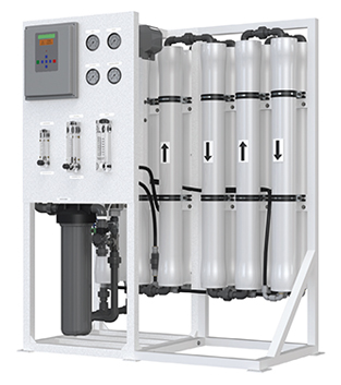
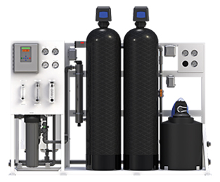
Reverse Osmosis System
Video
Product Images
BENEFITS
- Fully Equipped and Customizable
- Skid Mounted
- Decreased Size of Dimensional Footprint from Standard Reverse Osmosis Systems
- Components Easily Accessible
- Pre-Plumbed, Wired and Assembled
- Individually Tested and Preserved
- Low Operation and Maintenance Costs
- Easy Maintenance and Servicing
- 20% Less Energy Use than Standard Reverse Osmosis Systems
- 1-Year Limited Warranty
FEATURES
- S–150 Computer Controller
- LCD Backlit Display
- Pre-Treatment Lockout
- Tank Level Input
- Low Pressure Monitoring and Alarm
- Hour Meter
- TDS Monitoring
- Feed Flush
- AXEON Permeate and Concentrate Flow Meters
- AXEON Concentrate Recycle Flow Meter
- AXEON Pre-Filter 0-100 psi Panel Mounted Glycerin Filled Gauges
- AXEON Pump Discharge and Concentrate 0-300 psi Panel Mounted Glycerin Filled Gauges
- AXEON 5-Micron Sediment Pre-Filter
- AXEON HF5 – Series Ultra Low Energy Membrane Elements
- AXEON FRP– Series Membrane Housings (300 psi)
- AXEON by Pentair® 20" Big Grey Cartridge Housings
- Goulds® Multi-Stage Stainless Steel Booster Pump
- ASCO™ Composite Feed Solenoid Valve
- Feed Low Pressure Switch
- White Powder Coated Aluminum Frame
- Dual Chemical Pump Outlets
OPTIONS AND UPGRADES
- S–150 Expander Board
- S–150 Dual TDS Board and Sensor
- Filmtec® LCLE Membrane Elements
- AXEON SS–Series Membrane Elements
- AXEON NF3–Series Membrane Elements
- AXEON NF4–Series Membrane Elements
- AXEON HR3–Series Membrane Elements
- Hanna® BL 981411 pH Controller
- Permeate Flush
- Permeate Divert
- Permeate Sample Valves
- Pump Pressure Relief Valve
- Blending Valve
- High Pressure Tank Switch
- Wooden Crate
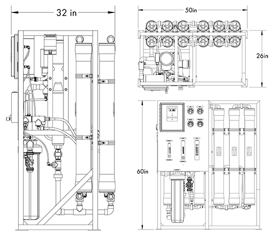
Notes:
- 1. All dimensions are given in inches.
- 2. R1–12140 AXEON model shown.
Notes:
- 1. Two check valves in parallel for models R1– 6140, R1– 8140, R1–10140 and R1–12140.
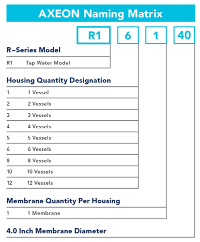
ARRAY SPECIFICATIONS
| MODELS | Vessel Array | Vessel Size | Vessel Quantity | Membrane Size | Membrane Quantity |
|---|---|---|---|---|---|
| R1–1140 | 1 | 4040 | 1 | 4040 | 1 |
| R1– 2140 | 1:1 | 4040 | 2 | 4040 | 2 |
| R1–3140 | 1:1:1 | 4040 | 3 | 4040 | 3 |
| R1–4140 | 1:1:1:1 | 4040 | 4 | 4040 | 4 |
| R1–5140 | 1:1:1:1:1 | 4040 | 5 | 4040 | 5 |
| R1–6140 | 2:2:2 | 4040 | 6 | 4040 | 6 |
| R1–8140 | 2:2:2:2 | 4040 | 8 | 4040 | 8 |
| R1–10140 | 2:2:2:2:2 | 4040 | 10 | 4040 | 10 |
| R1–12140 | 2:2:2:2:2:2 | 4040 | 12 | 4040 | 12 |
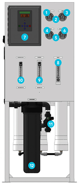
- 1
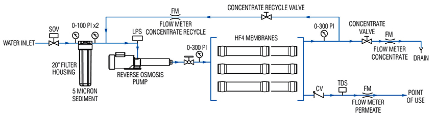
Filter In
Measures feed pressure which needs a minimum > 45 psi. Lower pressure can create low pressure faults.
- 2
Differential pressure is measured based on the Filter In and Filter Out and if it exceeds 15 psi then the filter must be replaced.
- 3
Filter Out
Measures pressure after the filter. This pressure must be above > 40 psi. Low pressure switch will shut off unit when it goes below < 15 psi.
- 4
Pump Pressure
Displays pressure after the RO Pump and before the first membrane. Max pressure is 200 psi.
- 5
If differential pressure on these two gauges shows above 15 psi per each membrane housing (ex. 3 membranes in series would add up to 45+ psi) then membrane likely is fouled. Clean or replace membranes.
- 6
Concentrate Pressure
Displays pressure after the last membrane.
- 7
S150 Controller
Monitors functions from TDS, temperature, rejection (with dual TDS Option) RO pump, pressures and solenoid valve. Voltage standard is 220 1 pH and optional 3 pH, voltage 380, 460, 575 VAC. This controller is UL/CUL certified.
- 8
Permeate
Shows the amount of water being produced in GPM (Gallons Per Minute), also known as Product Water.
- 9
Concentrate/Concentrate Valve
Measures flows of waste water using an integrated needle valve to adjust pressure and flows.
-
10
Concentrate Recycle/Concentrate Recycle Valve
Measures flows of recycled water from the waste water side for higher recovery using an integrated needle valve to adjust flows. This is used in conjunction with concentrate water.
- 11
Solenoid Valve
The ASCO brand solenoid is a composite valve that lets water in or stops based on RO demand. The size is 1" FNPT (female pipe thread). ALWAYS have the same size or larger pipe.
- 12
Sediment Filter
This uses a 4.5" x 20" filter that traps particulates as low as 5 microns using a 5 MIC filter.
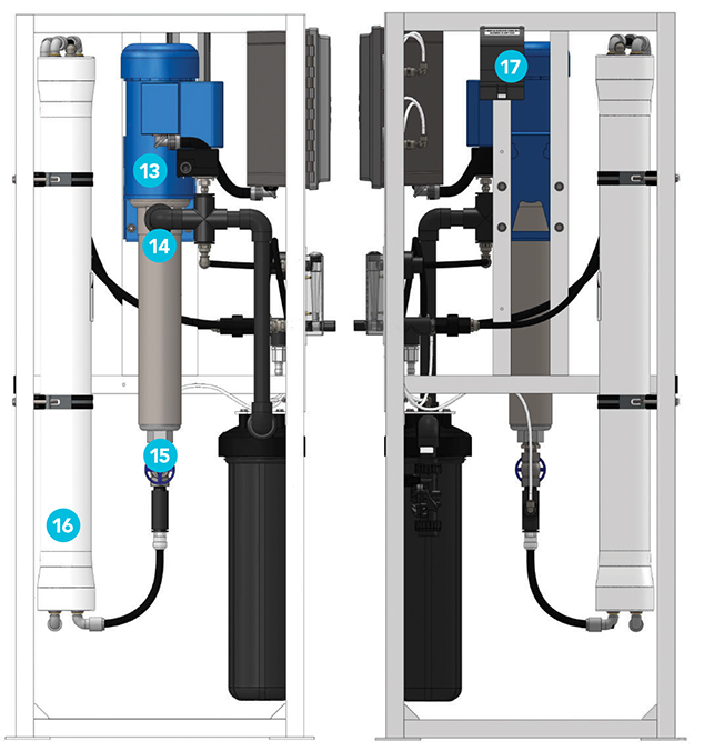
-
13
RO Pum
This produces the required pressure for the RO system. The R1 has two sizes: 1.5 hp for the R1–1140 to R1– 4140 and 3 hp for the R1–5140 to R1–12140.
- 14
Injection Port
This is for the injector used in a chemical injection system. This injects a chemical to help prevent fouling of the membrane. S200 is the chemical used to sequester hardness so it won't plug the membranes. Up to 300 GPG.
- 15
Pump Throttle Valve
This controls the flow and pressure from the pump. NEVER fully close this or damage will occur from heat and dead heading.
- 16
Fiberglass Pressure Valve
Stores membranes (HF5– 4040) that produce clean water.
- 17
Injection Power
Power source only for the chemical injection pump. It is not to be used for anything else or overloading can occur.
AXEON Reverse Osmosis Packaged Water Systems include configurations that produce 2,000 to 21,000 gallons of pure water per day. These systems arrive fully assembled, tested and ready for plug-in-play installation.
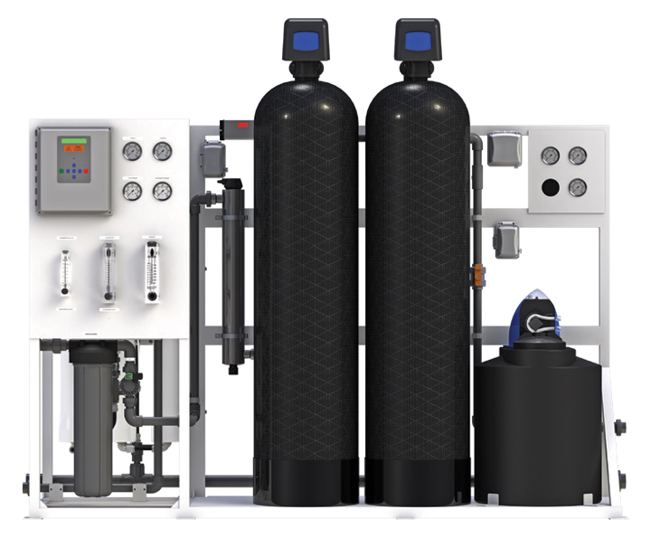
RWS – Series
Packaged Water Systems
SPECIFICATIONS
| MODELS | R1–1140 | R1–2140 | R1– 3140 | R1– 4140 | R1– 5140 | R1– 6140 | R1– 8140 | R1–10140 | R1–12140 |
|---|---|---|---|---|---|---|---|---|---|
| Design | |||||||||
| Configuration | Single Pass | Single Pass | Single Pass | Single Pass | Single Pass | Single Pass | Single Pass | Single Pass | Single Pass |
| Permeate Flow Rate (gpd / lpd) | 2000 | 2000 | 2000 | 2000 | 2000 | 2000 | 2000 | 2000 | 2000 |
| Permeate Flow Rate (gpm / lpm) | 29 | 45 | 56 | 63 | 68 | 56 | 63 | 68 | 71 |
| Rejection and Flow RatesB | |||||||||
| Permeate Flow Rate (gpd / lpd) | 1,800 / 6,813 | 3,600 / 13,627 | 5,400 / 20,441 | 7,200 / 27,254 | 9,000 / 34,068 | 10,800 / 40,882 | 14,400 / 54,509 | 18,000 / 68,137 | 21,600 / 81,764 |
| Permeate Flow (gpm / lpm) | 1.25 / 4.73 | 2.50 / 9.46 | 3.75 / 14.19 | 5.00 / 18.93 | 6.25 / 23.66 | 7.50 / 28.39 | 10.00 / 37.85 | 12.50 / 47.32 | 15.00 / 56.78 |
| Minimum Concentrate Flow (gpm / lpm) | 3 / 11.35 | 3 / 11.35 | 3 / 11.35 | 3 / 11.35 | 3 / 11.35 | 6 / 22.71 | 6 / 22.71 | 6 / 22.71 | 6 / 22.71 |
| Concentrate Recycle Flow Rate (gpm / lpm) | Up to 5 / 18.93 | Up to 5 / 18.93 | Up to 5 / 18.93 | Up to 5 / 18.93 | Up to 5 / 18.93 | Up to 5 / 18.93 | Up to 5 / 18.93 | Up to 5 / 18.93 | Up to 5 / 18.93 |
| Connections | |||||||||
| Feed Connection (in) | 1 FNPT | 1 FNPT | 1 FNPT | 1 FNPT | 1 FNPT | 1 FNPT | 1 FNPT | 1 FNPT | 1 FNPT |
| Permeate Connection (in) | 3/4 FNPT | 3/4 FNPT | 3/4 FNPT | 1 FNPT | 1 FNPT | 1 FNPT | 1 FNPT | 1 FNPT | 1 FNPT |
| Feed Connection (in) | 3/4 FNPT | 3/4 FNPT | 3/4 FNPT | 1 FNPT | 1 FNPT | 1 FNPT | 1 FNPT | 1 FNPT | 1 FNPT |
| Membranes | |||||||||
| Membranes Per Vessel | 1 | 1 | 1 | 1 | 1 | 1 | 1 | 1 | 1 |
| Membrane Quantity | 1 | 2 | 3 | 4 | 5 | 6 | 8 | 10 | 12 |
| Membrane Size | 4040 | 4040 | 4040 | 4040 | 4040 | 4040 | 4040 | 4040 | 4040 |
| Nominal TDS Rejection % | 98.5 | 98.5 | 98.5 | 98.5 | 98.5 | 98.5 | 98.5 | 98.5 | 98.5 |
| Vessels | |||||||||
| Vessel Array | 1 | 1:1 | 1:1:1 | 1:1:1:1 | 1:1:1:1:1 | 2:2:2 | 2:2:2:2 | 2:2:2:2:2 | 2:2:2:2:2:2 |
| Vessel Quantity | 1 | 2 | 3 | 4 | 5 | 6 | 8 | 10 | 12 |
| Pumps | |||||||||
| Pump Type | Multi-Stage | Multi-Stage | Multi-Stage | Multi-Stage | Multi-Stage | Multi-Stage | Multi-Stage | Multi-Stage | Multi-Stage |
| Motor HP | 1.5 | 1.5 | 1.5 | 1.5 | 3 | 3 | 3 | 3 | 3 |
| RPM @ 60Hz | 3450 | 3450 | 3450 | 3450 | 3450 | 3450 | 3450 | 3450 | 3450 |
| System Electrical | |||||||||
| Standard Voltage + Amp Draw | 220V, 60Hz, 1PH, 8.8A C | 220V, 60Hz, 1PH, 8.8A C | 220V, 60Hz, 1PH, 8.8A C | 220V, 60Hz, 1PH, 8.8A C | 220V, 60Hz, 1PH, 16A C | 220V, 60Hz, 1PH, 16A C | 220V, 60Hz, 1PH, 16A C | 220V, 60Hz, 1PH, 16A C | 220V, 60Hz, 1PH, 16A C |
| System Dimensions | |||||||||
| Approximate Dimensions D L x W x H (in /cm) |
26 x 26 x 60 / 73.66 x 66.04 x 154.94 | 26 x 26 x 60 / 73.66 x 66.04 x 154.94 | 26 x 26 x 60 / 73.66 x 66.04 x 154.94 | 32 x 26 x 60 / 78.74 x 66.04 x 154.94 | 32 x 26 x 60 / 78.74 x 66.04 x 154.94 | 32 x 26 x 60 / 78.74 x 66.04 x 154.94 | 32 x 26 x 60 / 78.74 x 66.04 x 154.94 | 32 x 26 x 60 / 78.74 x 66.04 x 154.94 | 32 x 26 x 60 / 78.74 x 66.04 x 154.94 |
| Approximate Weight (lbs) | 250 / 113.40 | 290 / 131.54 | 330 / 149.68 | 370 / 167.83 | 430 / 195.05 | 470 / 213.19 | 510 / 231.33 | 550 / 249.48 | 590 / 267.62 |
Test Parameters: 550 TDS Filtered (5-Micron), Dechlorinated, Municipal Feedwater, 65 psi / 4.50 bar Feed Pressure, 80 psi / 6.9 bar Operating Pressure, 77°F / 25°C, Recovery as stated, 7.0 pH. Data taken after 60 minutes of operation
A. Low temperatures and feedwater quality, such as high TDS levels will significantly affect the systems production capabilities and performance. Computer projections must be run for individual applications which do not meet or exceed minimum and maximum operating limits for such conditions.
B. Product flow and maximum recovery rates are based on feedwater conditions as stated above. Do not exceed recommended permeate flow.
C. Varies with motor manufacturer
D. Does not include operating space requirements.
OPERATING LIMITS E
| Maximum Feed Temperature (°F / °C) | 85 / 29 | Maximum Free Chlorine (ppm) | 0 |
| Maximum Feed Temperature (°F / °C) | 40 / 4 | Maximum TDS (ppm) | 2,000 |
| Maximum Ambient Temperature (°F / °C) | 120 / 49 | Maximum Hardness (gpg) | 0 |
| Minimum Ambient Temperature (°F / °C) | 40 / 4 | Maximum pH (continuous) | 11 |
| Maximum Feed Pressure (psi / bar) | 85 / 6 | Minimum pH (continuous) | 2 |
| Minimum Feed Pressure (psi / bar) | 45 / 3 | Maximum pH (cleaning 30 minutes) | 13 |
| Maximum Pressure (psi / bar) | 200 / 14 | Minimum pH (cleaning 30 minutes) | 1 |
| Maximum Feed Silt Density Index (SDI) | < 3 | Maximum Turbidity NTU | 1 |
E. System pressure is variable due to water conditions. Permeate flow will increase at a higher temperature and will decrease at a lower temperature.
THE RIGHT SOLUTION FOR YOU
Contact us today for more information about our products and services.
CONTACT US