
Reverse Osmosis System
Product Images
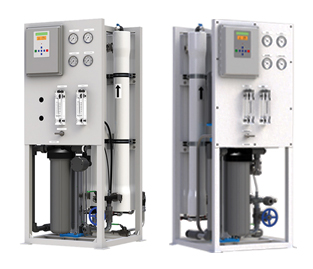
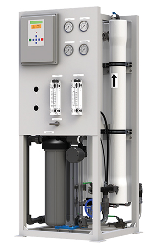
R2– SERIES REVERSE OSMOSIS SYSTEMS
AXEON® R2–Series Reverse Osmosis Systems are designed for durability and superior performance and are well-suited for treating well water and surface water containing dissolved solids up to 10,000 ppm. The R2-Series is specifically designed with a compact frame to fit into small areas such as utility rooms.
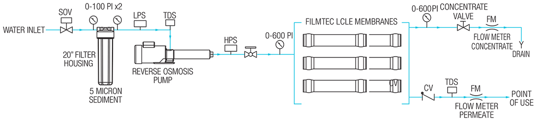
AXEON R2– Series Reverse Osmosis Systems s have been engineered for capacities ranging from 1,500 to 9,000 gallons per day. These systems include a computer processor with standard control functions for dual TDS monitoring, low pressure monitoring with alarm, pre-treatment lockout, feed flush and tanklevel input. These models feature high quality components such as a stainless steel multi-stage high pressure pump, low energy membrane elements, membrane housings rated at 450 psi and a cartridge housing with a 5-Micron sediment pre-filter.
Options available forthe R2– Series include permeate divert, variable frequency drive, a chemical injection system and a clean-in-place system.
BENEFITS
- Fully Equipped and Customizable
- Expandable and Skid Mounted
- Decreased Size of Dimensional Footprint
- Components Easily Accessible
- Pre-Plumbed, Wired and Assembled
- Individually Tested and Preserved
- Low Operation and Maintenance Costs
- Easy Maintenance and Servicing
- 1-Year Limited Warranty
FEATURES
-
S –150 Computer Controller
- LCD Backlit Display
- Pre-Treatment Lockout
- Tank Level Input
- High Pressure Monitoring with Alarm
- Low Pressure Monitoring with Alarm
- Dual TDS Monitoring
- Feed Flush
- AXEON Permeate and Concentrate Flow Meters
- AXEON Pre-Filter 0-100 psi Panel Mounted Glycerin Filled Gauges
- AXEON Post-Filter 0-100 psi Panel Mounted Glycerin Filled Gauges
- AXEON 0-600 psi Glycerin-Filled Pump Discharge and Concentrate Pressure Gauges
- AXEON 5-Micron Sediment Pre-Filter
- Pentair® Single O-Ring Heavy-Duty Filter Housing
- Filmtec® LCLE Low Energy Membrane Elements
- AXEON FRP– Series Membrane Housings (450 psi)
- Permeate Sample Ports
- Vertical Multi-Stage Stainless Steel Booster Pump
- Plastomatic Feed Solenoid Valve
- Feed Low Pressure Switch
- Pump High Pressure Switch
- Clean-in-Place (CIP) Ports
- Victaulic® Style Fittings
- Permeate Sample Ports
- High Pressure Stainless Steel Tubing and Fittings
- White Powder Coated Aluminum Frame
OPTIONS AND UPGRADES
- S –150 Expander Board
- Variable Frequency Drive (VFD)
- Filmtec® LCHR Membrane Elements
- Pump Pressure Relief Valve
- Blending Valve
- Permeate Divert Valve
- Permeate Flush
- Chemical Pump Outlet
- Hanna® BL 981411 pH Controller
- Hanna® BL 982411 ORP Controller
- High Pressure Tank Switch
- Caster Wheels
- Wooden Shipping Crate
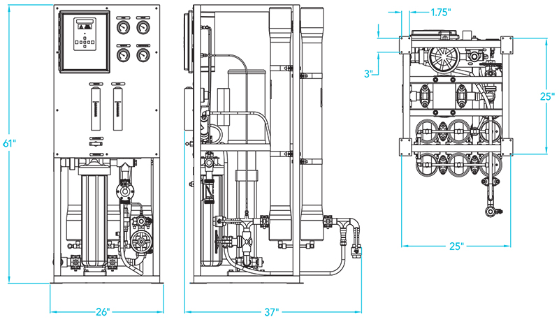
Notes:
- 1. All dimensions are given in inches.
- 2. R2– 6140 AXEON model shown.
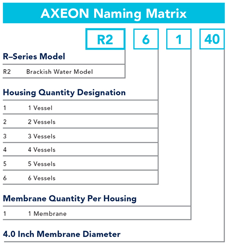
ARRAY SPECIFICATIONS
| Model | Vessel Array | Vessel Size | Vessel Quantity | Membrane Size | Membrane Quantity |
|---|---|---|---|---|---|
| R2–1140 | 1 | 4040 | 1 | 4040 | 1 |
| R2– 2140 | 1:1 | 4040 | 2 | 4040 | 2 |
| R2– 3140 | 1:1:1 | 4040 | 3 | 4040 | 3 |
| R2– 4140 | 1:1:1:1 | 4040 | 4 | 4040 | 4 |
| R2– 5140 | 1:1:1:1:1 | 4040 | 5 | 4040 | 5 |
| R2– 6140 | 1:1:1:1:1:1 | 4040 | 6 | 4040 | 6 |
SPECIFICATIONS
| MODELS | R2–1140 | R2– 2140 | R2– 3140 | R2– 4140 | R2– 5140 | R2– 6140 |
|---|---|---|---|---|---|---|
| Design | ||||||
| Configuration | Single Pass | Single Pass | Single Pass | Single Pass | Single Pass | Single Pass |
| Feedwater SourceA | TDS < 10,000 ppm | TDS < 10,000 ppm | TDS < 10,000 ppm | TDS < 10,000 ppm | TDS < 10,000 ppm | TDS < 10,000 ppm |
| Standard Recovery Rate % | 15-25 | 30-40 | 40-50 | 40-55 | 40-60 | 40-65 |
| Rejection and Flow RatesB | ||||||
| Nominal Salt Rejection % | 99.2 | 99.2 | 99.2 | 99.2 | 99.2 | 99.2 |
| Permeate Flow Rate (gpm / lpm) | 1.04 / 3.94 | 2.08 / 7.89 | 3.13 / 11.83 | 4.17 / 15.77 | 5.21 / 19.72 | 6.25 / 23.66 |
| Minimum Concentrate Flow Rate (gpm / lpm) | 4.04 / 15.30 | 5.08 / 19.20 | 6.13 / 23.20 | 7.17 / 27.10 | 8.21 / 31.10 | 9.25 / 35.00 |
| Maximum Feed Flow (gpm / lpm) | 14.00 / 53.00 | 14.00 / 53.00 | 14.00 / 53.00 | 14.00 / 53.00 | 14.00 / 53.00 | 14.00 / 53.00 |
| Minimum Concentrate Flow Rate (gpm / lpm) | 3.00 / 11.36 | 3.00 / 11.36 | 3.00 / 11.36 | 3.00 / 11.36 | 3.00 / 11.36 | 3.00 / 11.36 |
| Connections | ||||||
| Feed FNPT (in) | 1 FNPT | 1 FNPT | 1 FNPT | 1 FNPT | 1 FNPT | 1 FNPT |
| Permeate Tubing (in) | 3/4 FNPT | 3/4 FNPT | 3/4 FNPT | 1 FNPT | 1 FNPT | 1 FNPT |
| Concentrate Tubing (in) | 3/4 FNPT | 3/4 FNPT | 3/4 FNPT | 1 FNPT | 1 FNPT | 1 FNPT |
| CIP (in) | 3/4 FNPT | 3/4 FNPT | 3/4 FNPT | 3/4 FNPT | 3/4 FNPT | 3/4 FNPT |
| Membranes | ||||||
| Membranes Per Vessel | 1 | 1 | 1 | 1 | 1 | 1 |
| Membrane Quantity | 1 | 2 | 3 | 4 | 5 | 6 |
| Membrane Size | 4040 | 4040 | 4040 | 4040 | 4040 | 4040 |
| Vessels | ||||||
| Vessel Array | 1 | 1:1 | 1:1:1 | 1:1:1:1 | 1:1:1:1:1 | 1:1:1:1:1:1 |
| Vessel Quantity | 1 | 2 | 3 | 4 | 5 | 6 |
| Pumps | ||||||
| Pump Type | Multi-Stage | Multi-Stage | Multi-Stage | Multi-Stage | Multi-Stage | Multi-Stage |
| Motor HP | 3 | 3 | 3 | 5 | 5 | 5 |
| RPM @ 60Hz (50 Hz) | 3450 (2900) | 3450 (2900) | 3450 (2900) | 3450 (2900) | 3450 (2900) | 3450 (2900) |
| System Electrical | ||||||
| Standard Voltage + Amp Draw | 220V, 60Hz, 1PH, 14.5AC | 220V, 60Hz, 1PH, 14.5AC | 220V, 60Hz, 1PH, 14.5AC | 220V, 60Hz, 3PH, 14.2AC | 220V, 60Hz, 3PH, 14.2AC | 220V, 60Hz, 3PH, 14.2AC |
| High Voltage Service + Amp Draw |
220V, 50Hz, 1PH, 17.4AC 220V, 50Hz, 3PH, 0.6AC 220V, 60Hz, 3PH, 9AC 460V, 60Hz, 3PH, 5AC |
220V, 50Hz, 1PH, 17.4AC 220V, 50Hz, 3PH, 0.6AC 220V, 60Hz, 3PH, 9AC 460V, 60Hz, 3PH, 5AC |
220V, 50Hz, 1PH, 17.4AC 220V, 50Hz, 3PH, 0.6AC 220V, 60Hz, 3PH, 9AC 460V, 60Hz, 3PH, 5AC |
220V, 50Hz, 3PH, 16.1AC 460V, 60Hz, 3PH, 7AC |
220V, 50Hz, 3PH, 16.1AC 460V, 60Hz, 3PH, 7AC |
220V, 50Hz, 3PH, 16.1AC 460V, 60Hz, 3PH, 7AC |
| System Dimensions | ||||||
| Approximate Dimensions D L x W x H (in /cm) | 27 x 26 x 61 / 69 x 66 x 155 | 27 x 26 x 61 / 69 x 66 x 155 | 30 x 26 x 61 / 75 x 66 x 155 | 32 x 26 x 61 / 80 x 66 x 155 | 32 x 26 x 61 / 80 x 66 x 155 | 32 x 26 x 61 / 80 x 66 x 155 |
| Approximate Weight (lbs/Kg) | 560 / 250 | 590 / 270 | 620 / 280 | 650 / 300 | 680 / 310 | 700 / 320 |
Test Parameters: 10,000 TDS Filtered (5-Micron), Dechlorinated, Municipal Feedwater, 65 psi / 4.50 bar Feed Pressure, 350 psi / 24.13 bar Operating Pressure, 77°F / 25°C, Recovery as stated, 7.0 pH. Data taken after 60 minutes of operation.
A. Low temperatures and feedwater quality, such as high TDS levels will
significantly affect the systems production capabilities and performance.
Computer projections must be run for individual applications which do not
meet or exceed minimum and maximum operating limits for such conditions.
B. Product flow and maximum recovery rates are based on feedwater
conditions as stated above. Do not exceed recommended permeate flow.
C. Varies with motor manufacturer
D. Does not include operating space requirements.
OPERATING LIMITSE
| Maximum Feed Temperature (°F / °C) | 85 / 29 | Maximum Free Chlorine (ppm) | 1 |
| Maximum Feed Temperature (°F / °C) | 40 / 4 | Maximum TDS (ppm) | 10,000 |
| Maximum Ambient Temperature (°F / °C) | 120 / 49 | Maximum Hardness (gpg) | < 1 |
| Minimum Ambient Temperature (°F / °C) | 40 / 4 | Minimum pH (continuous) | 11 |
| Maximum Feed Pressure (psi / bar) | 85 / 6 | Minimum pH (continuous) | 2 |
| Minimum Feed Pressure (psi / bar) | 45 / 3 | Minimum pH (cleaning 30 minutes) | 13 |
| Maximum Operating Pressure (psi / bar) | 400 / 28 | Minimum pH (cleaning 30 minutes) | 1 |
| Maximum Feed Silt Density Index (SDI) | < 3 | Maximum Turbidity (NTU) | < 1 |
E. System pressure is variable due to water conditions. Permeate flow will increase at a higher temperature and will decrease at a lower temperature.
THE RIGHT SOLUTION FOR YOU
Contact us today for more information about our products and services.
CONTACT US