
X1–SERIES REVERSE OSMOSIS SYSTEMS
AXEON® X1–Series Reverse Osmosis Systems are designed as a cost-effective solution to the growing demand of tap and well water for applications in food and beverage, pharmaceutical, healthcare, microelectronics, power, chemicals and agriculture.
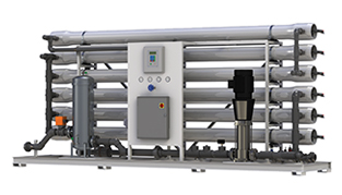
With models ranging from 22 to 120 gallons per minute (32,000 to 190,000 gallons per day), the smart, clean utilitarian industrial design of the AXEON X1–Series allow for convenient installation, user-friendly operation and ease of maintenance. These skid-mounted, package systems are pre-plumbed and pre-wired on a powder-coated steel frame complete with a pre-programmed computer controller, TDS probes and panelmounted pressure gauges and flow instrumentation, allowing for straight forward system monitoring and control. AXEON X1–Series Systems utilize energy-efficient ultra low energy membranes with 10% greater membrane surface area than standard 8 inch reverse osmosis elements, thus producing more pure water.
FEATURES
- S –150 Pre-Programmed Computer Controller A
- S – 200 Pre-Programmed Computer Controller with VFD (Variable Frequency Drive) B
- 8 inch Low Energy Membrane Elements
- 8 inch Fiberglass Membrane Housings with Stainless Steel Side Ports (300 psi)
- 5-Micron Sediment Cartridge Filters
- Multi-Cartridge 304L Stainless Steel Cartridge Housing
- Permeate and Concentrate Rotameters A
- Permeate and Concentrate Digital Paddlewheel SensorsB
- Pre- and Post- Filter Pressure Gauges
- Pump Pressure and Concentrate Pressure Gauges
- Feed and Permeate TDS
- Composite Feed Solenoid ValveA
- Motorized Feed ValveB
- Stainless Steel Globe Throttling ValvesA
- Low and High Pressure Shut-Off Switches
- Efficient Vertical Stainless Steel Multi-Stage Pump
- Powder Coated Carbon Steel Frame
- Sch80 PVC Piping
- Clean-In-Place (CIP) Ports with Valves
- Permeate Sample Valves
- Chemical Feed Ports
- Chemical Feed Power Outlet
- 220VAC 3PH 60HZ
OPTIONS AND UPGRADES
- S – 200 Computer ControllerC
- VFDC
- Programmable Logic Controller (PLC) with Touch Screen
- Permeate and Concentrate Digital Paddlewheel SensorsC
- PVC Feed Motorized Ball ValveC
- Concentrate Recycle Loop with Flow Meter
- PVC Permeate Divert Motorized Ball Valve
- Permeate Flush
- pH Sensor
- ORP Sensor
- Chemical Feed System
- Clean-In-Place Skid-Mounted System
- Voltage Options: 220VAC 3PH 50Hz, 380VAC 3PH 50Hz, 460VAC 3PH 60Hz
A. Standard on Models X1–2280, X1–3280, X1– 4280, X1– 5280.
B. Standard on Models X1–3480, X1– 4480, X1– 5480, X1– 6480.
C. Option available for Models X1–2280, X1– 3280, X1– 4280, X1– 5280. Standard on larger models.
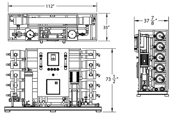
Notes:
- 1. All dimensions are given in inches.
- 2. Dimensions given for X1–2280 through X1–5280.
(X1 – 5280 pictured)
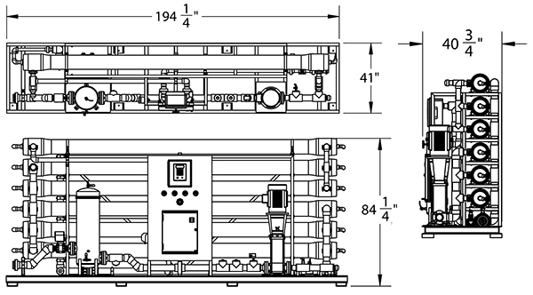
Notes:
- 1. All dimensions are given in inches.
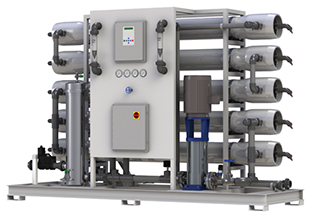
- 2. Dimensions given for X1-3480 through X1-6480.
(X1-6480 pictured)
SPECIFICATIONS
| MODELS | X1– 2280 | X1– 3280 | X1– 4280 | X1– 5280 | X1– 3480 | X1– 4480 | X1– 5480 | X1– 6480 |
|---|---|---|---|---|---|---|---|---|
| Design | ||||||||
| Configuration | Single Pass | Single Pass | Single Pass | Single Pass | Single Pass | Single Pass | Single Pass | Single Pass |
| Feedwater Source (ppm) D | TDS < 2,000 | TDS < 2,000 | TDS < 2,000 | TDS < 2,000 | TDS < 2,000 | TDS < 2,000 | TDS < 2,000 | TDS < 2,000 |
| Standard Recovery % | 61 | 70 | 75 | 75 | 75 | 75 | 75 | 75 |
| Recovery with Concentrate Recycle (gpm %) | 80 | 80 | 80 | N/A | N/A | N/A | N/A | N/A |
| Rejection and Flow RatesE | ||||||||
| Nominal Salt Rejection % | 99 | 99 | 99 | 99 | 99 | 99 | 99 | 99 |
| Permeate Flow Rate (gpm / lpm) | 20 / 75.71 | 30 / 113.56 | 40 / 151.42 | 50 / 189.27 | 60 / 227.13 | 80 / 302.83 | 100 / 378.54 | 120 / 454.25 |
| Minimum Concentrate Flow Rate (gpm / lpm) | 14 / 53 | 14 / 53 | 14.6 / 55 | 18.3 / 69 | 22 / 83 | 29 / 111 | 36.6 / 139 | 44 / 167 |
| Connections | ||||||||
| Feed Connection (in) | 2 FNPT | 2 FNPT | 2 FNPT | 2 FNPT | 3 FNPT | 3 FNPT | 3 FNPT | 3 FNPT |
| Permeate Connection (in) | 1 1/2 FNPT | 1 1/2 FNPT | 2 FNPT | 2 FNPT | 2 1/2 FNPT | 2 1/2 FNPT | 3 FNPT | 3 FNPT |
| Concentrate Connection (in) | 1 1/4 FNPT | 1 1/4 FNPT | 1 1/4 FNPT | 1 1/4 FNPT | 1 1/2 FNPT | 1 1/2 FNPT | 2 FNPT | 2 FNPT |
| Clean-in-Place Port (in) | 1 1/2 FNPT | 1 1/2 FNPT | 1 1/2 FNPT | 1 1/2 FNPT | 2 FNPT | 2 FNPT | 2 FNPT | 2 FNPT |
| Chemical Feed Port (in) | 1/2 FNPT | 1/2 FNPT | 1/2 FNPT | 1/2 FNPT | 1/2 FNPT | 1/2 FNPT | 1/2 FNPT | 1/2 FNPT |
| Membranes | ||||||||
| Membranes Per Vessel | 2 | 2 | 2 | 2 | 4 | 4 | 4 | 4 |
| Membrane Quantity | 4 | 6 | 8 | 10 | 12 | 16 | 20 | 24 |
| Membrane Size | 8040 | 8040 | 8040 | 8040 | 8040 | 8040 | 8040 | 8040 |
| Vessels | ||||||||
| Vessel Array | 1:1 | 1:1:1 | 1:1:1:1 | 2:1:1:1 | 2:1 | 2:1:1 | 3:1:1 | 3:2:1 |
| Vessel Quantity | 2 | 3 | 4 | 5 | 3 | 4 | 5 | 6 |
| Pumps | ||||||||
| Pump Type | Vertical Multi-Stage Centrifugal Pump | Vertical Multi-Stage Centrifugal Pump | Vertical Multi-Stage Centrifugal Pump | Vertical Multi-Stage Centrifugal Pump | Vertical Multi-Stage Centrifugal Pump | Vertical Multi-Stage Centrifugal Pump | Vertical Multi-Stage Centrifugal Pump | Vertical Multi-Stage Centrifugal Pump |
| Motor HP / KW | 10 / 7.5 | 10 / 7.5 | 10 / 7.5 | 10 / 7.5 | 15 / 11 | 15 / 11 | 20 / 11 | 20 / 11 |
| System Electrical | ||||||||
| Standard Voltage + Amp DrawC | 208V-230V, 60Hz, 3PH, 28A-27A F | 208V-230V, 60Hz, 3PH, 28A-27A F | 208V-230V, 60Hz, 3PH, 28A-27A F | 208V-230V, 60Hz, 3PH, 28A-27A F | 208V-230V, 60Hz, 3PH, 40.5A-27A F | 208V-230V, 60Hz, 3PH, 40.5A-27A F | 208V-230V, 60Hz, 3PH, 49AF | 208V-230V, 60Hz, 3PH, 49AF |
| System Dimensions | ||||||||
| Approximate Dimensions G L x W x H (in /cm) | 112 x 35 x 74 / 284 x 89 x 188 | 112 x 35 x 74 / 284 x 89 x 188 | 112 x 35 x 74 / 284 x 89 x 188 | 112 x 35 x 74 / 284 x 89 x 188 | 194 x 41 x 78 / 493 x 104 x 198 | 194 x 41 x 78 / 493 x 104 x 198 | 194 x 41 x 78 / 493 x 104 x 198 | 194 x 41 x 84 / 493 x 104 x 213 |
| Approximate Weight (lbs) | 1,285 / 583 | 1,435 / 651 | 1,585 / 719 | 1,735 / 787 | 2,005 / 910 | 2,275 / 1,032 | 2,645 / 1,200 | 2,910 / 1,320 |
Test Parameters: 550 TDS Filtered (5-Micron), Dechlorinated, Municipal Feedwater, 65 psi / 4.50 bar Feed Pressure, 100 psi / 6.9 bar Operating Pressure, 77°F / 25°C, Recovery as stated, 7.0 pH. Data taken after 60 minutes of operation
D. Low temperatures and feedwater quality, such as high TDS levels will significantly affect the systems production capabilities and performance. Computer projections must be run for individual applications which do not meet or exceed minimum and maximum operating limits for such conditions.
E. Product flow and maximum recovery rates are based on feedwater conditions as stated above. Do not exceed recommended permeate flow.
F. Varies with motor manufacturer
G. Does not include operating space requirements.
OPERATING LIMITS D
| Design Temperature (°F / °C) | 77 / 25 | Maximum SDI Rating (SDI) | < 3 |
| Maximum Feed Temperature (°F / °C) | 85 / 29 | Maximum Free Chlorine (ppm) | 0 |
| Maximum Feed Temperature (°F / °C) | 40 / 4 | Maximum TDS (ppm) | 0 |
| Maximum Ambient Temperature (°F / °C) | 120 / 49 | Maximum Hardness (gpg) | 11 |
| Minimum Ambient Temperature (°F / °C) | 40 / 4 | Minimum pH (continuous) | 2 |
| Maximum Feed Pressure (psi / bar) | 85 / 6 | Minimum pH (continuous) | 13 |
| Minimum Feed Pressure (psi / bar) | 45 / 3 | Minimum pH (cleaning 30 minutes) | 1 |
| Maximum Operating Pressure (psi / bar) | 200 / 18.7 | Maximum Turbidity (NTU) | < 1 |
H. System pressure is variable due to water conditions. Permeate flow will increase at a higher temperature and will decrease at a lower temperature.
THE RIGHT SOLUTION FOR YOU
Contact us today for more information about our products and services.
CONTACT US